|
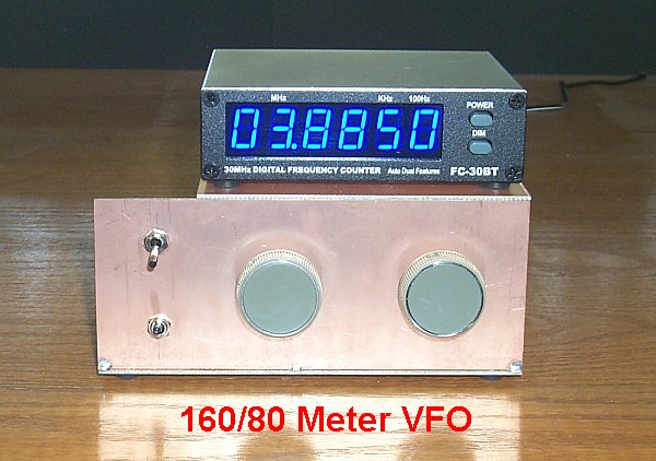
This high stability VFO was designed for use with a digital-drive Class D 160 and 80 meter AM Transmitter described some time ago. A similar VFO was built by Steve, WA1QIX, for use with his Class E transmitters and was the inspiration for this project. The major focus of this project was to enhance frequency stability. Circuit ideas and details are applicable to VFOs used with other transmitters. At room temperature (65 - 75 deg. F.) this VFO drifts less than 50 Hz from a cold start and after warm up drifts around the set frequency less than 2 Hz/hr on 75 meters - half this amount on 160.* Credit Doug DeMaw, W1FB(SK), for many of the design ideas presented here. The circuit has been adapted for a number of different frequency ranges with equally impressive results.
Why not get with the times and build a DDS? A DDS certainly has advantages in terms of frequency setabililty and stability but one major drawback - spurs (spurious signals) - make it less than ideal as a signal source. Spur levels of -75 dBc (dB relative to the carrier) are not uncommon with a 'commercial grade' DDS. While 75 dB down may sound pretty good, consider this: You're running legal limit power to a decent antenna and your signal is a 'strapping' loud 40 dB over S9 at some location. A spur that is 75 dB down will be an S3 - S4 signal level at that location! While this might go unnoticed under noisy band conditions, it will draw attention on a quiet band. There will be a number of spurs that fall in and out of band and they go on and off with your carrier making it easy to track you down! A well designed VFO will have spectral purity approaching that of a crystal with a quick drop off to a noise shelf of -140 dBc or better...and with no spurs. Phase noise measurement of this VFO shows it to be only a few dB noisier than a 'benchmark' HP8640B.
The schematic diagram can be found at 160/80 meter VFO. The 7 - 8 MHz oscillator stage is a JFET Clapp design that has been optimized for frequency stability. The oscillator stage is followed by a broadband dual-gate MOSFET buffer and 'squared up' by the input section of a 74HC4046. On 80 meters the output frequency is 7 - 8 MHz which feeds the divide-by-2, flip-flop phase splitter at the input of the Class-D transmitter deck. For 160 meters the signal is divided by two. An additional divide by two provides a signal for the frequency counter. A 6' coaxial cable connects the VFO to the rf deck.
A number of design ideas contribute to the excellent oscillator stability. The series tuned Clapp arrangement allows larger L values to be used (compared to a parallel tank) so stray inductances have less effect on circuit performance. The tank inductor is wound on a -6 powdered iron core and exhibits a Q greater than 200. This material has the lowest temperature coefficient of the powdered iron and ferrite materials. An air coil made from small Miniductor stock may be a better choice if the VFO will see extreme temperatures. The coarse and fine tuning capacitors are paralleled by three fixed-value polystyrene capacitors. Splitting the rf current among multiple capacitors reduces the rf current and heating in each capacitor aiding frequency stability. Polystyrene capacitors have proven to be more temperature stable than silver mica types. Micas are good but tend to have somewhat unpredictable temperature coefficients - even from the same batch. Disc ceramics NPOs can also be used but should be limited to only a small portion of the padding capacitance and only then to optimize the oscillator drift characteristics.
The use of relatively large feedback capacitors helps mask changes in FET capacitance. Two polystyrene capacitors in parallel (180 and 270 pF) make up the required feedback capacitance and reduce rf current and heating through each capacitor. The 1N4148 diode is used as a gate clamp limiting the positive excursion of the sinewave and to provide stabilizing bias. The VFO was designed around parts on hand. A J310 FET is shown, but any rf JFET like an MPF-102 or 2N5486 should work. The MFE201 can be replaced by most any dual-gate FET in the 40673 or 3N200 family.
There's not much to aligning the VFO other than setting it to cover the desired frequency range. The turns on the coil can be slightly compressed or expanded and adjustment can be made to the values of the three fixed-value tank capacitors to accomplish this. If similar components are used, the frequency stability should be good 'right out of the box'. Final tweaking for minimum drift starts with a full VFO warm up (about a half hour) and then noting the direction and speed of any drift. Trial and error changes to the three fixed-value tank capacitors should stabilize the oscillator. It may be necessary to replace one or more of the polystyrene capacitors with a silver mica and/or ceramic NPO. Not all silver micas drift in the same direction so it's handy to have several on hand to try. Heat created while soldering components will make quite a change in frequency. Once a change is made restart the oscillator and check back in a half hour to see what effect your change made. Take notes on the drift of each capacitor combination - this will help to guide the way to just the right combination. Patience during this phase of the project will be rewarded.
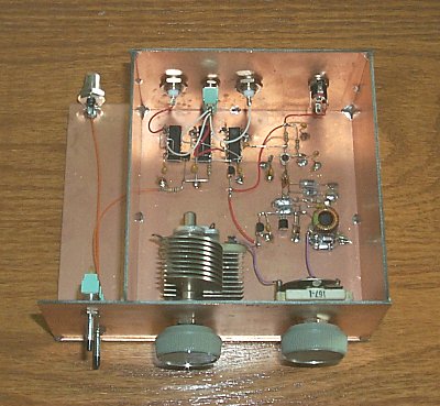
As one would expect, virtually everything associated with the oscillator stage affects frequency stability and attention to detail is key. Variable capacitors should be chosen for their small size, quality, bearing surfaces and good wiper contact. The toroid tank inductor should be coated with Q dope to hold the turns securely in place. A 12 VDC regulated wall wart powers the VFO. Remote mounting the power supply keeps that heat source away from the VFO. A 78L08 further regulates the oscillator stage. The VFO should be installed in a metal enclosure to shield it from rf fields and air currents and a rugged enclosure will make for a more stable VFO than a flimsy one. Enclosing the tank circuit in a separate sub-enclosure to shield it from heat generating components should provide additional frequency stability.
|