Hafler P3000 / 9505 Input & Output Transformers
For 73, 137 and 475 kHz

Transmission Line Transformers

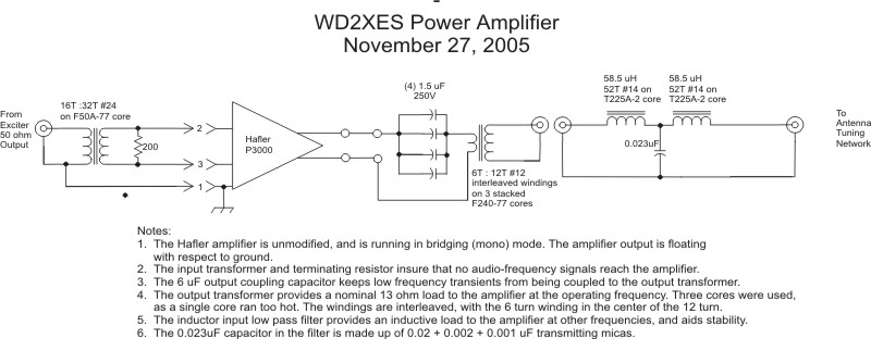
The addition of 73 kHz as an FCC Part 5 low frequency 'band' prompted a look at the Hafler P3000 and Hafler 9505 output transformer. The original output transformer was designed by John Andrews, W1TAG, for operation on 137 kHz. With some additional capacitors in series the output transformer could be operated at 500 kHz. This meant that two different setups were required - one for each band. With the addition of a third band, this meant that three different transformer setups would be required. Since the Hafler amplifiers cover all three bands without bandswitching, a single output transformer that would handle all three bands seemed a reasonable goal. The new output transformer described here meets that requirement. A new input transformer is also described.

The new output transformer design utilizes a 1:4 transmission line transformer that is broadband. Ferrite sleeve cores are used to 'load' the transmission lines - not as a 'medium' to couple power. This means less core material is required and they run cool even at high power levels. Following the 1:4 transmission line transformer is a 1:1 coaxial balun. A number of sources claim that the 1:4 transmission line transformer is inherently a balun - balanced input to unbalanced output - but that doesn't appear to be the case. Without the 1:1 balun, under high power operation, one of the two core sets shows a rise in temperature. The 1:1 balun on the output eliminates this heating.

A new input transformer using a trifilar winding on a 75 material ferrite core extends the low frequency response and minimizes leakage reactance.

Construction

Schematics for the new transformers are available here. TL1 and TL2 form the 1:4 transmission line transformer. Each half is wound on two 75 material ferrite sleeve cores that are taped or epoxied together. As noted on the schematics these are wound with 50 ohm coaxial cable. Purists may question the use of 50-ohm coaxial cable in the 1:4 transformer - 25 ohm coaxial cable [sqrt (12.5 x 50)] would be more appropriate. In this application, over a limited bandwidth, the difference is insignificant. Purists can make their own 25 ohm line by removing the RG-400 center conductor and replacing it with #14 stranded insulated wire. I've done this on other projects but it isn't necessary here. Keep the 1:4 transformer windings equal in length. One half should be a mirror image of the other. Several different capacitor values were evaluated with 4) 3.9 uF capacitors in parallel providing the best performance.

For clarity, the winding count is given as 'passes' instead of turns. A pass is defined as the coax passing through either core. The 7 pass windings are admittedly a bit of a tight fit.

Output Transformer

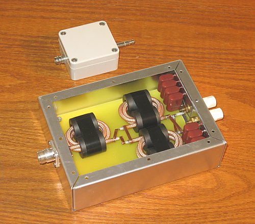
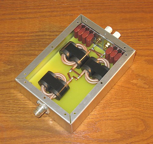
The output transformer was constructed in a 7" X 5" X 2" aluminum chassis. Binding posts are used on the 12.5 ohm side - a short length of twisted pair (#14 stranded) connects the transformer to the Hafler amplifier. An N connector is used on the 50 ohm side which in turn attaches to the appropriate low pass filter. C1 - C8 are mounted to a circuit board that connects directly to the binding posts. A piece of scrap FR4 circuit board with the copper etched off is mounted above the chassis bottom by standoffs. TL1, TL2 and TL3 are held in position with small dabs of RTV. There's no need to follow this construction technique - at these frequencies almost any arrangement will work. Inititial testing was carried out in the open on a benchtop with results indistinguishable from the packaged version.

Input Transformer

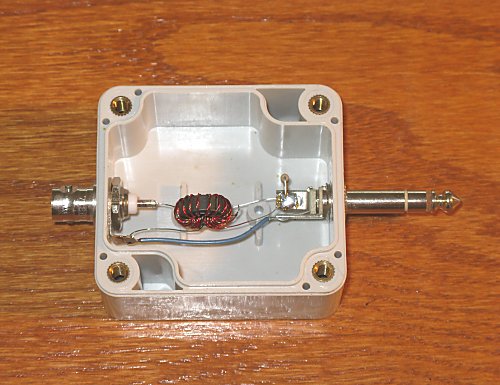
The input transformer is housed in a 2-1/4" X 2-1/2" X 1-3/8" plastic box. The 50 ohm input is a BNC connector and a 1/4" stereo phone plug plugs directly into the Hafler input. A hole is drilled and tapped to accept the stereo phone plug which is then epoxied in place. Originally it wasn't clear whether or not a ground would be used between the exciter and the Hafler so a plastic box was used to allow for a 'ground lift'. It turned out that a ground connection has been used ever since the original testing. There's no reason not to use a shielded box, however no problems have been noted using a plastic box. Feeding signal to the balanced inputs no doubt helps deter common mode signals.

Measurements

The following measurements of the output transformer were done with the aid of an AIM4170. The 50 ohm side of the transformer was terminated and the 12.5 ohm side was swept over the frequency range from 50 kHz - 550 kHz. The graph below shows a transformer that accurately transforms 50 ohms to 12.5 ohms with only a small amount of leakage reactance at the high frequency end.

TL transformer plot

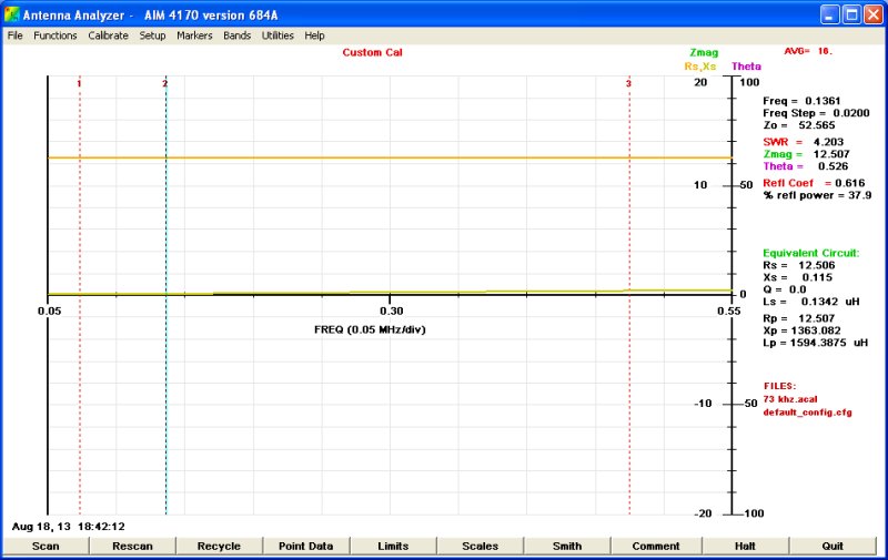
Readings were taken at several frequencies of interest and are presented in the table below. Note that the curves are smooth and 'well behaved' indicating no frequency dependant 'anomolies'.

MarkerFrequencyRsXsSWRReturn Loss
173 kHz12.4950.0721.0150.78
2136 kHz12.5080.1121.0146.96
3475 kHz12.5030.4141.0335.62

Back to W1VD WD2XNS WE2XGR/2 home page