|
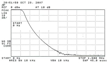
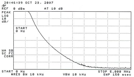
The low-pass filters described here were built for use at WD2XNS and WE2XGR/2 to be used after Class D and linear amplifiers. The LF version has a cutoff frequency of 138 kHz and the MF version 515 kHz. Both filters have been tested to power levels in excess of 1000 watts and should be capable of handling significantly more power.
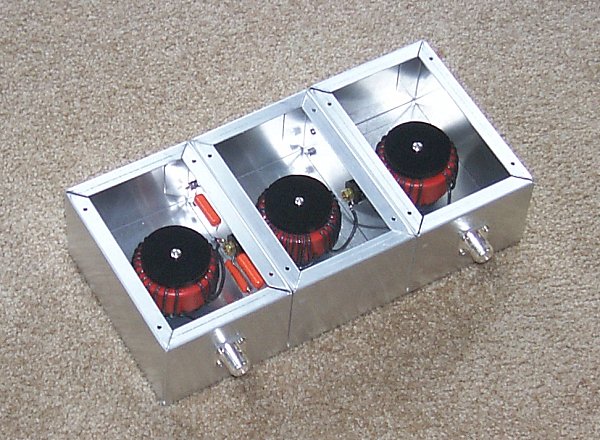
Schematic diagram and parts list of the low-pass filters can be found at 138 & 515 kHz LPF. Both filters share identical construction techniques and are housed in three Bud AC-430 3" X 4" X 6" aluminum chassis which are held together with machine screws. Small delrin shoulder washers and brass threaded rod were used to make the 'feedthrough' connection from one compartment to the next. Although the toroids are self shielding, stop-band attenuation at higher frequencies is improved by using multiple compartments. Capacitors are mounted in their associated end compartments. The inductors are supported on delrin standoff insulators. N connectors are used for the input and output connections.
The inductors for 138 kHz are wound with #14 solid enameled wire because of the large number of turns required. While there is sufficient room on the end cores for all of the turns, the center inductor has a number of the turns placed on a second layer. Any core that is wound with enameled wire should first be wrapped with 3M glass-epoxy tape to prevent chafing of the insulation. The same glass-epoxy tape should also be used between layers in the center inductor.
For 515 kHz the inductors can be wound with solid #14 THHN plastic insulated wire as shown. The turns on the center inductor just fill the core and a second layer is not required. Since plastic insulated wire is used, wrapping the cores with glasss-epoxy tape is not required.
|