|
Jennings RJ1A Vacuum Relay Measurements |
|||||||||||||||||||||||||||||||||||||||||||||||||||||||||||||||||||||||||||||||||||||||||||||||||||||||||||
|
|||||||||||||||||||||||||||||||||||||||||||||||||||||||||||||||||||||||||||||||||||||||||||||||||||||||||||
|
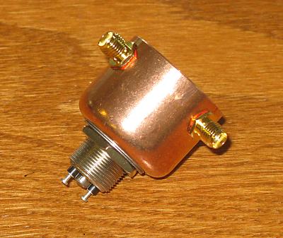
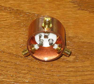
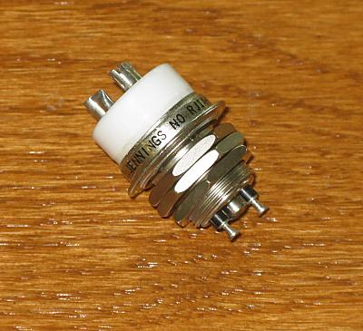
After the successful modification of a Heathkit SB-220 for 6 meter operation, an upgrade of the T/R relay to allow QSK operation is now being considered. The 'defacto' relay for high-power QSK at HF is the Jennings RJ1A or equivalent. Unfortunately these excellent relays are only spec'd to 32 MHz ... and those specifications lack information other than voltage and current capability. A copy of the Jennings RJ1A data sheet can be found at RJ1A Specifications.
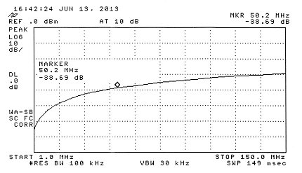
The first measurement was for relay isolation - from the common connection to the normally open connection with the relay de-energized. A second test from common to the normally closed connection with the relay energized produced results that were indistiguishable from the first test. An HP8595E spectrum analyzer and tracking generator were used for the measurement. All ports were terminated in 50 ohms. The wideband spectrum display can be seen below.
Readings were taken at several amateur bands of interest and are presented in the table below. Note that the curve is smooth and 'well behaved' indicating no frequency dependant 'anomolies'.
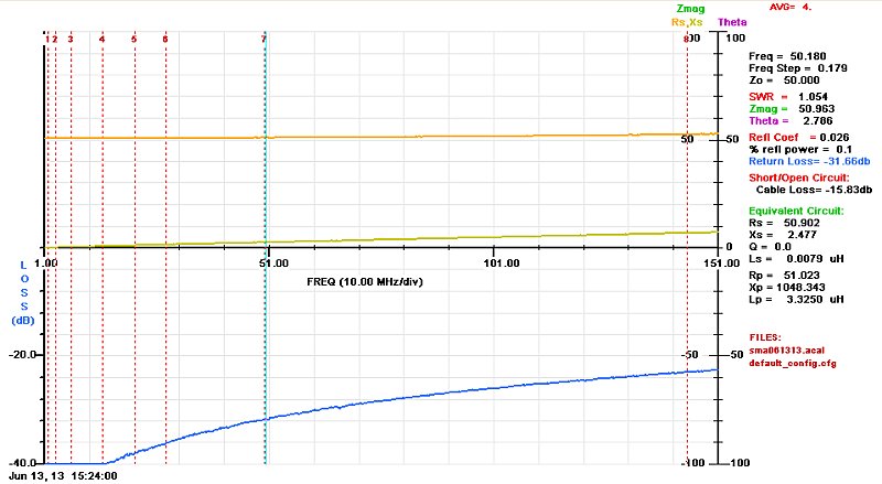
The following impedance/return loss measurement was made using an AIM4170 analyzer. All ports were terminated in 50 ohms. The display shows the frequency range from 1 MHz to 150 MHz.
Readings were taken at several amateur bands of interest and are presented in the table below. Note that the curves are smooth and 'well behaved' indicating, again, no frequency dependant 'anomolies'.
Based on the info from Jennings and the measurements presented here, performance appears to be adequate for operation at 50 MHz. A writeup on the SB-220 modifications for 6 meter operation including the use of the RJ1A relays will be forthcoming ... once the 6-meter sporadic E season winds down!
|