Squires Sanders SS-1R Amateur Band Receiver Performance Test

Squires Sanders SS-1R

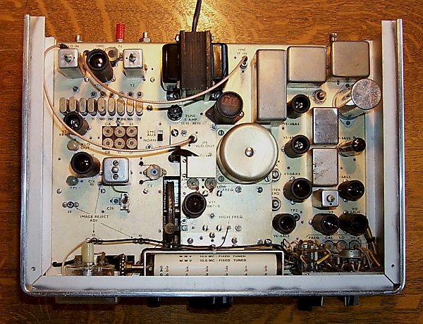
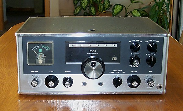
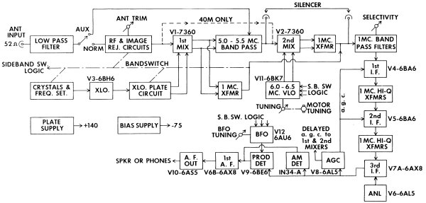
"The Squires-Sanders, Inc. SS-1R is a high performance communications receiver explicitly designed for amateur band operation on 80 through 10 meters. A completely new approach to front-end design produces superb freedom from cross-modulation and overload, while the frequency precision and stability sets new standards for amateur equipment." That's how the Squires-Sanders advertising read on the SS-1R - a receiver produced in relatively low numbers. Most receiver enthusiasts I've talked to have never had the opportunity to use one and express great interest in its performance and the capabilities of the 7360 beam deflection tubes used as the heart of the receiver front end. A search of the literature and the internet turns up little detailed information on the receiver other than an article by William Squires in September 1963 QST and the Recent Equipment review in May 1964 QST. While Squires presented measurements for cross modulation, blocking and noise figure, his measurements predate the standardized receiver test procedures that began in the mid 70s. The goal of this project was to test a properly functioning receiver, using current measurement techniques, and compare its performance to other popular receivers.

A table of receiver specifications can be found at SS-1R Receiver Specifications.

After months of searching, and a bit of luck, an SS-1R in essentially unmolested condition was found. What followed was a six week, couple hour a night project to return the receiver to 'factory' performance levels.

SS-1R Block Diagram

Receiver Particulars

The block diagram of the SS-1R above shows the unusual circuit arrangement. At the time most receivers had already moved away from dual rf amplifier stages in favor of a single stage but Squires went a step further - no rf amplifier at all. Signals from the antenna pass through a low-pass filter and the 'rf & image reject circuits' straight to the first and second 7360 beam deflection mixers. These mixers were thought to be the 'hot ticket' with low cross modulation and an excellent noise figure. Squires circuit applied balanced local oscillator injection to the deflection plates, incoming signal to the No. 1 grid and the output was taken in push pull fashion from the plates. Three i-f filter bandwidths are available: 5 kc for AM - i-f tuned circuits; 2.5 kc for SSB - crystal lattice filter; and .35 kHz for CW - a pair of crystals.

The remainder of the receiver is pretty standard fare with a couple exceptions. Diode logic switching of capacitors in the BFO allow the USB and LSB switch positions to provide proper sideband reception regardless of the band selected. Similar circuitry in the VLO allows the tuning dial to correctly read the frequency of the suppressed carrier.

A slide rule tuning dial displays frequency in 100 kHz increments and in between those marks turns counters indicate frequency to the nearest kc by displaying digits 0 - 99. In the picture above the turns counter can be seen to the right of the main tuning dial. There is a second counter, that operates in reverse, to the left of the dial for 80 meters where tuning is in the opposite direction. Only the appropriate turns counter for the band in use is displayed - the other is blocked from view.

Also of interest is the motor driven VLO. The main frequency dial has a tuning rate of 10 kc per revolution that is nice for cw and SSB tuning but is a real pain when moving to the other end of the band. Push buttons on each side of the main tuning dial stand ready to engage the motor drive to briskly change frequency - at a rate of about 60 kc per second. The motor introduces no electrical noise so it doubles as neat band scan tool!

Frequency stability is listed as " Less than 500 cps drift from cold start. Typical warm-up time is less than 5 minutes. Less than 100 cps frequency change thereafter with 105 to 125 V line variation." Measurements confirm the spec to be accurate but how Squires managed this is a bit of a mystery. There are no voltage regulators and no 'trick' circuitry is apparent.

Receiver Performance Testing

The main goal of this project was to return the receiver to 'factory' performance so that sensitivity and dynamic range measurements could be carried out. It was indeed lucky that a Squires Sanders proprietary 'Service Information Test Procedure' manual was available from http://www.manualman.com. The test and alignment section is fifteen pages encompassing swept first and second i-f alignment, crystal oscillator alignment, frequency adjustment, BFO alignment, VLO alignment, front-end alignment, S-meter adjustment, i-f output alignment, 2nd mixer balance, 1st mixer balance and image rejection circuit adjustments for each band. Returning the receiver to factory performance levels without benefit of the manual would have been a much more difficult exercise.

Once it was determined that the receiver was working to 'factory' specifications, sensitivity, blocking and two-tone dynamic range measurements were carried out on 80, 40 and 20 meters. The results are as follows:

Band MDS Blocking Two-tone D.R.
(20 kHz) (20 kHz)
 
80 meters -134 dBm 108 dB 89 dB
40 meters -136 dBm 120 dB 89 dB
20 meters -136 dBm 110 dB 90 dB

How does the SS-1R stack up? Comparing the SS-1R to its predecessors on a list of Boat Anchor Receiver Tests it does quite well. MDS is not as good as the BA receivers tested but quite acceptable for HF use. The SS-1R dynamic range numbers beat all those on the list, however the R-390A wins the blocking dynamic range competition.

Measurements on a number of other receivers can be found on this 1980 list of Receiver Dynamic Range Measurements. On 20 and 80 meters the SS-1R scores slightly ahead of the Collins S-line receivers in two tone IMD but slightly lower in blocking dynamic. 40-meter performance was ahead of the S-line receivers in both categories. Note that the SS-1R beats most other receivers on the list - some manufactured as much as 15 years after the SS-1R.

For a list of more recent receivers one can consult Robert Sherwood's Receiver Test Data.

Examination of 7360 LO Injection Level

Of particular interest is the 10 dB improvement in blocking dynamic range measured on the 40 meter band. The SS-1R receiver operates in single conversion on 40 meters - the first mixer is bypassed. Operating the receiver on 40 meters provided a convenient means to study just a single stage of 7360 mixer.

RCA 7360 application notes recommend 10V p-p oscillator injection be applied to the deflection plates for best mixer performance. Squires reports in his article, "The r.m.s. oscillator voltage at a deflection electrode can be from one to ten volts. The higher voltages produce slightly greater conversion gain but may lead to harmonic mixing problems caused by curvature of the deflection electrode characteristics. Three volts is adequate and near optimum." Levels measured in this particular SS-1R receiver are 4V p-p at the first mixer and 6V p-p at the second mixer. So which is the best level to use?

In an effort to answer this question the receiver sensitivity and dynamic range was tested in single conversion mode (40 meters) with the internal VLO temporarily replaced by an HP-8640B signal generator and amplifier so that the LO injection could be easily adjusted. The 40-meter measurements with different values of LO are noted below.

LO level

MDS Blocking Two-tone D.R.
(20 kHz) (20 kHz)
 
  6V p-p -136 dBm 120 dB 89 dB
10V p-p -138 dBm 129 dB 94 dB
14V p-p -138 dBm 132 dB 94 dB

Blocking dynamic range was the biggest beneficiary of increased LO, however all three measurements showed improvement. Even higher LO levels (above 14V p-p) were tried and further improvement in blocking dynamic range was noted but at a diminished rate of improvement. Somewhat surprising was the 2-dB improvement in noise floor. Noise levels increased for LO levels below 8V p-p and got significantly worse for LO levels below 4V p-p.

These tests indicate that the SS-1R might be an even better performer had it not been starved for LO. Why Squires elected to go with lower LO levels is unknown but it may be related to second harmonic mixing or the desire to keep birdies at a very low level. The specifications for spurious are 'None at stated sensitivity' which is '1/2 microvolt or better for 10 dB signal-to-noise ratio measured with 5 kc bandwidth on 10 meters'. Further study and measurements of the 7360 mixer would no doubt produce interesting information.

Fairly simple modifications have been devised to boost both oscillators to the 10V p-p level. As time permits these mods will be incorporated into the receiver and new sensitivity and dynamic range measurements will be made.

Construction

Since the SS-1R is a seldom seen, low production number receiver, a few words and pictures describing construction are in order. The main chassis, shielded compartments and all brackets are gold alodined aluminum. The chassis slides into a one piece aluminum extrusion that makes up the left side, front and right side of the case and is bent with a radius at each corner. The chassis, complete with all controls attached, can be slid clear of the front and side panels once the knobs have been removed. This would seldom be required as there is excellent access once the top and bottom cover assembly is removed. Two shielded compartments can be seen below deck - one for the VLO and the other for the crystal oscillator / second mixer. The quality of components and construction approaches that of the Collins S-line receivers.

Squires Sanders SS-1R

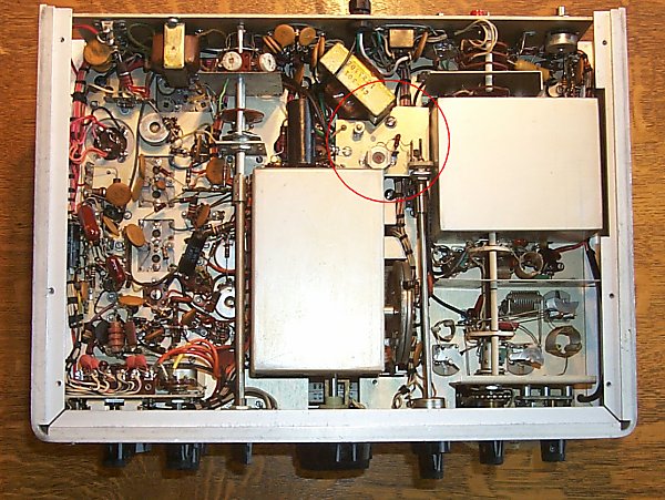
A curious addition to this receiver is the i-f notch filter shown in the red circle. Adjustment of the notch is via a knob that is concentric with the rf gain control. This circuit does not appear on the two schematic diagrams that are available. Initially it was thought that this was a user added feature but on closer inspection it looks to be a factory job. The components used including the fixed value capacitors, pot core, resistors, teflon tie points and concentric knobs are all factory parts. Perhaps this was a custom factory addition.

Squires Sanders SS-1R

Squires also manufactured innovative accessories for the SS-1R. The SS-1S 'Noise Silencer', detected impulse noise in the wide (500 kHz) first i-f, amplified and shaped these impulses and used them to provide blanking action in the narrow second i-f. It was sold as a separate unit and was conveniently housed in an SS-1RS matching speaker. The SS-1V Video Bandscanner is a band scope that allows monitoring of the entire band in use. The displayed signals don't move as the receiver is tuned, but instead a marker 'pip' indicates the receive frequency. Squires also manufactured a shortwave broadcast version of the receiver identified as the SS-IBS.

While the SS-1R incorporated a number of innovative ideas and performs very well there is one caveat that should be mentioned. The spec sheet calls out a 52 ohm antenna. Most receivers 'of the day' had one or more rf amplifiers and at least a couple sets of rf tuned circuits. With the typical abundance of gain these receivers can use most any matched or unmatched antenna. The SS-1R, with no rf amplifier and only one rf tuned circuit in the grid of the mixer that handles both impedance matching and image rejection, an antenna with close to the correct impedance is a must. Unmatched random wire antennas will yield disappointing receiver sensitivity and image rejection. In those situations a receive antenna matching circuit will be required. Squires sold a 'Broadband Antenna Matcher' as an accessory item for the SS-1R.

Unfortunately William Squires, W2PUL was killed in a small plane crash not long after the SS-1R product line went into production. He certainly demonstrated a different approach to receiver design and one can only imagine what other receiver innovations might have been forthcoming.


Jay Rusgrove W1VD