|
The 137 & 500 kHz Class-D Kilowatt transmitter described here was built for use at WD2XNS (136 - 138 kHz) and WE2XGR/2 (505 - 515 kHz) to transmit modes that don't require linear amplification - cw, QRSS and various FSK modes. Transmissions that require linear amplification are handled by a linear phasing exciter and Hafler 9505 power amplifier - details are elsewhere on this website.
|
|
|
|
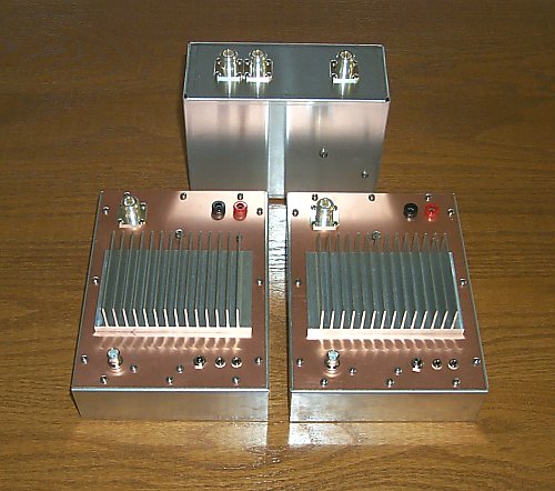
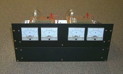
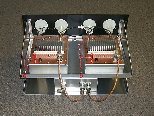
The kilowatt transmitter consists of the three modules shown above - two 500-watt rf decks and a power combiner. A low-pass filter after the combiner keeps harmonics at very low levels. The rf decks and combiner operate with very high efficiency and have proven to be extremely reliable logging many hours of cw contacts and beacon mode operation. Modular construction was chosen over an all-in-one-box kilowatt transmitter as this allows convenient reconfiguration of the station - whether to carry out experimentation or to reallocate components to another project or band.
Don't need a kilowatt? Build just one deck and dispense with the power combiner. Need more than a kilowatt? Build additional modules and modify the power combiner. Modular design does offer that advantage!
RF Decks
The rf decks are designed to operate on both 137 and 500 kHz and measured efficiencies are about 95% on both bands. The only component change required when switching bands are the capacitors used in the snubber network. They could be made switch selectable or plug in - perhaps utilizing crystal sockets. Since these decks are reasonably inexpensive to produce, building a set for each band is not out of the question. Counting the two sets of prototypes that were built before the finished units shown here, six transmitter modules in all have been built so far. All exhibited identical performance.
Credit for the starting point of this design goes to G0MRF, G3YXM and VE7TIL. In fact, the gate drive circuit bears a striking resemblence to that used by VE7TIL. When something works well there's little reason to make changes! The main differences are the use of Class D voltage mode instead of current mode, an output transformer that works efficiently on both 137 and 500 kHz, "T" type low-pass filters as required for voltage mode operation, and a hybrid combiner that works on both bands.
The schematic diagram of the rf deck can be found at 137 & 500 kHz 500-Watt RF Deck . A digital signal at 2 times the desired output frequency is applied to the 74F74, a divide by two flip flop that provides both phases required to drive the IR2110. The IR2110 is a high and low side driver with a number of useful features including the ability to be keyed, low voltage lockout and matched propagation delay that prevents FET cross conduction. Gate drive to the 34N20s is via short lengths of twisted pair.
The output transformer is constructed on a single FT-240-77 core that is wrapped with Scotch 27 glass cloth electrical tape. The secondary winding, 18 turns #14 solid THHN, is wound first. The primary winding consists of 5 turns of #16 zip cord equally spaced over the secondary winding. Zip cord makes an acceptable substitute for hand wound bifilar. This transformation ratio is correct for a 50 volt supply @ 10 amperes and 500 watt power level. For other power/impedance levels adjust the number of turns on the 18 turn secondary. A rotary switch could be used to select a number of different secondary taps.
Construction
Construction techniques used for housing the rf decks harken back to that used in the 60's for homebuilt VHF equipment. The entire rf deck is built on a piece of circuit board material that is then mounted in a aluminum chassis providing rf shielding. This construction method allows ease of service - the circuit board and all components mounted to it can be removed from the chassis. Modifications and experiments are easily carried out as there is a complete ground plane on which to solder components. FETs and snubber resistors are mounted directly to the heat sink through cutouts in the circuit board and Silpads are used between the FETs and the heatsink providing excellent thermal conductivity. Relatively small heatsinks provide sufficient cooling for cw and QRSS modes without forced air. Continuous full-power, key-down modes such as MFSK will require a small muffin fan or larger heatsinks.
A circuit board was fabricated for the gate drive components to make future duplication of the transmitter modules easier, however, 'dead bug' style construction technique worked perfectly well in the prototype decks.
|
|
|
|
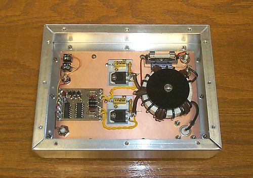
A Bud AC-1413 6" X 8" X 2" aluminum chassis is used as the enclosure. The top of the chassis is cut out to the same dimesions as the bottom opening. Pem nuts are pressed into holes in the chassis which allow easy removal of transmitter assembly or bottom cover. Perforated aluminum is used for the bottom cover to allow some airflow around the transformer, although after extended key down operation the core temperature rises only about 10 degrees above ambient. The transformer is supported above the circuit board by two delrin discs and a center rod assembly. Digital input is through a BNC connector and an N connector is used for the rf output. High voltage DC is supplied through a pair of banana jacks and 12 VDC from a regulated wall wart enters via a coaxial power connector. Key and 'keying sync' jacks are miniature phone types.
The Power Combiner
The power combiner is an adaptation of zero degree hybrid couplers made popular by Helge Granberg of Motorola for use in high-power, broadband HF amplifiers. A detailed presentation can be found in Motorola application note AN749. This combiner provides greater than 25 dB port-to-port isolation on both 137 and 500 kHz. No changes are required when switching from one band to the other. A schematic of the combiner can be found at 137 & 500 kHz Combiner . There are basically two parts to the combiner - ferrite loaded balun lines and a broadband step up transformer.
If both input signals are of the same phase and amplitude little power is dissipated in the resistor. In operation with the two identical transmitters described here there is a only a perceptable rise in the resistor temperature. If one transmitter should fail, the remaining transmitter will continue operating. However, under these circumstances only half its power will make it to the antenna - the remainder will be dissipated in the resistor! If you plan on running this redundant 'backup' mode for any period of time LARGE resistors attached to a LARGE heatsink will be required. Fault detection is used on both transmitters in my installation - if either one goes down they both turn off. The terminating resistor only sees significant power during the brief fault shutdown period.
|
|
|
|
Construction
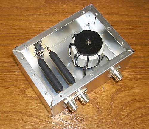
A Bud AC-429 5" X 7" X 3" aluminum chassis is fitted with three N connectors. The two input connectors support one end of the balun lines and the resistors on the opposite wall of the enclosure support the other ends. The ferrite loaded balun lines are made by placing 14) FT-50-W cores over 4" lengths of RG-142/U teflon coaxial cable. FT-50 sized cores are a loose fit on the cable so two layers of Raychem RNF100-1/4" heat shrink tubing are first applied to the cable. Cores are then slid over the layers and are held in place with a third piece of heat shrink tubing - RNF100-1/2". No power is dissipated in the ferrite cores so they run cool. The terminating resistance is a pair of 50-ohm, 100-watt power film resistors that are bolted to the aluminum chassis.
Three FT-240-77 cores are used for the 1:2 transformer. Each core is individually wrapped with Scotch 27 tape and then the three cores are wrapped together with another layer. #12 solid THHN wire was used for both windings. The transformer is mounted using two delrin discs and a center rod assembly as in the transmitter modules. The 1:2 transformer runs warm, but not hot, to the touch after continous operation.
By adding additional input balun sections, additional terminating resistors and changing the transformer impedance ratio, any number of transmitters can be combined. A set of four 500-watt modules and a suitable combiner would certainly get noticed on the bands...or possibly set your antenna afire!
Additional Notes
Low pass filters for 137 and 500 kHz used after the combiner are 5-section "T" type filters. They have been previously described for use with the Hafler 9505 linear amplifier and can be found at
LF and MF Kilowatt+ Low Pass Filters . "T" type low pass filters (not pi type) must be used with voltage mode Class D amplifiers.
Each transmitter has its own keying circuit so that it can can be used as a stand alone transmitter. When two transmitters are operated in parallel only one amplifier is keyed by the station keyer or computer serial port and the other amplifier is keyed via the 'keying sync' interconnection between the two transmitter modules. This eliminates the possibility of keying time errors. The keyed waveform is reasonably 'hard' but no key clicks have been reported.
|
|
|
|
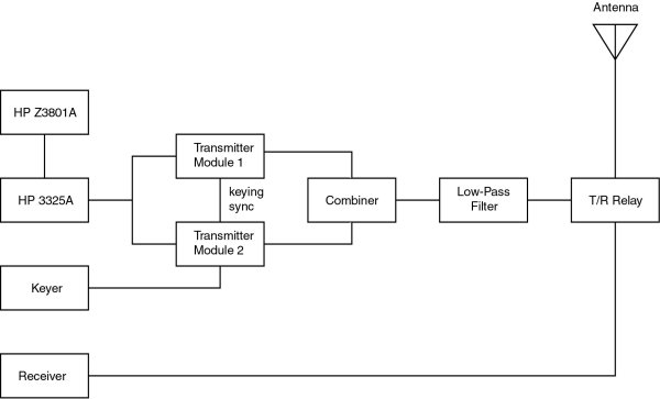
A diagram of the setup is shown above. The signal source driving the two modules is a GPS referenced HP3325A synthesizer/function generator. The output of the generator is split with a "T" connector - one side feeding each module. Alternatively a VFO or DDS could be used to drive the modules - TTL drive at 2 times the output frequency is all that's required.
Two identical homebrew, unregulated, linear-type supplies power the two transmitter modules. Both power supply transformers receive ac mains power through a Powerstat and this provides a convenient method for adjusting power output. The amplifiers are stable at all power levels but efficiency suffers some with operation at other than the design power level.
Spectral Analysis
|
|
|
|
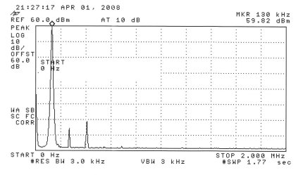
The spectral display above shows the 137 kHz output of the two modules combined with low-pass filtering. The top line of the graticule is +60 dBm (1 kW) and the vertical display is 10 dB per division.
|
|
|
|
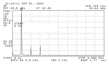
The spectral display above shows the 500 kHz output of the two modules combined with low-pass filtering. The top line of the graticule is +60 dBm (1 kW) and the vertical display is 10 dB per division.
Picture of the prototype setup shows the 'dead bug' style construction used for the gate drive circuitry. These transmitters were operated unshielded for a period of time and no interference problems were noted.
|
|
Back to W1VD WD2XNS WE2XGR/2 home page
|
|
| | | | | | |